| Lightweight Material |
| Design&Manufacture |
| Performance Testing |
| Static mechanical properties |
| Dynamic Mechanical Properties |
| Nonlinear Vibration |
| Vibro-acoustic Properties |
| Flow and Heat Transfer Properties |
| Electromagnetic Properties |
| Bioinspired engineering and biomechanics |
| Multifunctional Optimization and Collaborative Design |
Flow and Heat Transfer Properties
1. New lattice-core ventilated brake disk fabrication and relative research
Heavy truck may face high temperature and thus facing brake ablity decrease, brake disk fatige and break, thermal induced vibration and increase on brake disk abrasion. Our team come up with a new conception on applying the lightweight lattice metal, which can possess both good mechanics/thermal properties, for the ventilated brake disk core so that we can achieve both weight decreasing and thermal dissipation optimization. We have successfully fabricated the ventilated brake dick with WBD core and X core (figure 1) and cast basic research on it.
The experiment shows that the temperature of abration is far less than the commercial brake disk (figure 2(a)). Upon the steady state experiment experiment, its overall performance is 16%-36% than its opponent (图2(b)). Thus, the new brake disk is better. In addition, the infrared experiment (figure 3) shows that the WBD core can decrease the unninity of temperature inside the abration circle and can make the radial and circumferential temperature distribution more balance (figure 4), that can help decrease the thermal stress of the circle and incresse the ability of anti-fatigue and thermal vibretion resistance.
The WBD core has more poriness (90%) than fin core (nearly 70%), hovever, the pressure loss when flow get through the WBD core is more than the pressure loss when flow get through the fin core(figure 5(a)). We can consider that the WBD core can enhance the mix of flow and thus can improve its ability. Besides, the superficial area of WBD core is forth times than fin core which can increase the convective area. WBD core can increase the work area of the core and can overcome its shortcoming of high resistance.
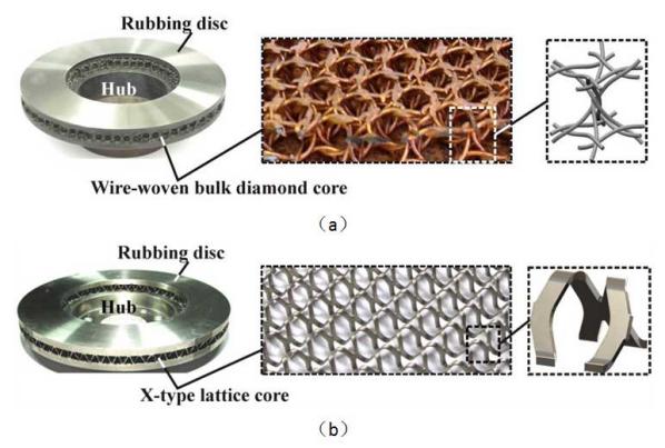
Figure 1 new lattice core disk for ventilating and brake:(a)X lattice core type;(b)WBD core type

Figure 2 heat dissipation property of new WBD brake disk:(a)abration surface temperature variation along tiwh time;(b)steady state heat transfer properties

Figure 3 abration loop inner surface temperature distribution: experimental data:(a)commercial fin core brake
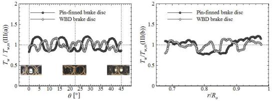
Figure 4 circumferential and radial temperature distribution:(a)circumferential distribution;(b) radial distribution
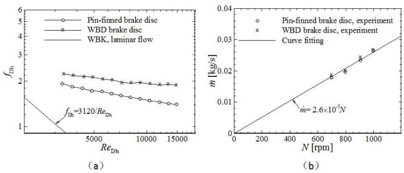
Figure 5 flow resistance and aerodynamic property for the new WBD brake disk:(a)flow resistance property;(b)aerodynamic property
2. Convective heat transfer property of new X-type lattice core sandwich panel
Compared with other lattice core fabrication methods, the steel palte net punch forming has prosperous prospect because of its low material waste, simple process. Compared with thraditional pyramid lattice core, our new X-type lattice core has better mechanical property. We have cast experiment and numerical simulationon its inner thermal heat-transfer properties and compared with LFM and Kagome core. The outcome shows that the new core has better heat thansfer in OA direction than others, say, 100% than OB direction, 36% than LFM core and 10% than Kagome core (figure 7(a)). And the new core has smaller thermal conduction coefficient than others. X-type lattice core can better improve if fabricated with the same material.
Simulation outcomes show that since X lattice has unique characteristic in OA direction(figure 7), there is spiral flow generated in the flow field which can inhance the heat transfer in the leeside. Besides, with the same porosity, there is larger area in the windward side and better heat transfer property on it. Consequently, OA direction has better heat transfer effect.
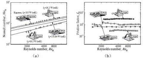
Figure 6 convective and flow property for X type core:(a)heat transfer;(b)flow resistance
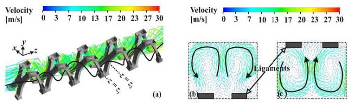
Figure 7 spiral flow properties of the X core in its OA direction:(a)overall flow;(b) velosity image in the z = z1 plane;(c) velosity image in the z = z2 plane
3. The heat-transfer properties of cylinder smelting furnace under the tube inpingement jet cooling
Compared with other cooling techniques, jet impingement cooling is high in heat-transfer efficiency and simple in construction. Confronted with the cooling process of foam aluminum fabrication, we have cast research on the heat-transfer properties of cylinder melting furnace under the single-tube impingement, inclined tube impingement and multi-tube impingement, and analysed the influence of impingement distance, cylinder curvature, inclined angle and numbers of impingement tubes. The outcome shows that under the single tube impingement, when the relative curvature is small (diamater of the cylinder is smaller than the diameter of the tube), the heat-transfer coefficient distribution of the surface of the tube will behave like a uniform flow around a circular cylinder, which means that the secondary heat-transfer peak is led to by flow seperation. When the relative curvature is large, the heat transfer properties will behave like a tube impinge on a flat plate, which mens that the secondary heat-transfer peak is led to by transition. As the tube jet impinge the cylinder furnace at a specific angle, the secondary heat-transfer peak of downstream rigion will decrease with the inclined angle increase, which is different from the inclined flat plate inpingement. At the same time, we have found the influence of inclined angle to the stagnation point is relavant to the impingement distance. Inside the potential core, the stagnation region will increase with a increasing inclined angle. While outside the region, the outcome is on the contrary. By comparing the cooling properties of single tube and dual tube under the same flow flux, we have found that the single tube impingement is better when the diameter of the cylinder furnace is 14 times less than the diameter of impingement tube.
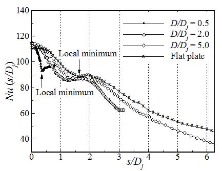
Figure 8 Nu distribution on different curvature cylinder surface, inside the single tube impingement potential core
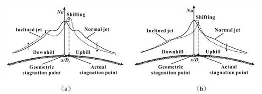
Figure 9 influence of inclined angle on convective cylinder heat transfer:(a)with cylinder in the potential core;(b)with cylinder out of the potential core
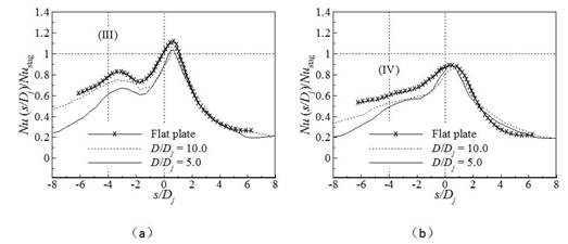
Figure 10 local heat transfer coefficient distribution of different curvature syrface under different inclined angle(z=2D;Re=20000)。(a)with cylinder in the potential core;(b)with cylinder out of the potential core
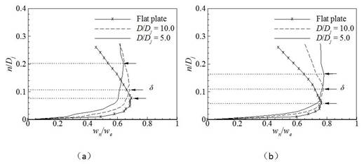
Figure 11 boundary layer thickness and velocity distribution of boundary layer of the inclined jet for differentcurvature cylinder:(a)with cylinder in the potential core;(b)with cylinder out of the potential core
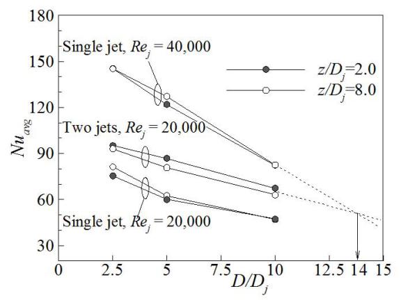
Figure 12 comparison of surface heat transfer for single tube jet and multi-tube jet with the same flow flux
4. Full analytical model for the effective heat transfer coefficient of through-hole metal foam
We have established a peorid structure, which is based on a tetrakaidecahedron cell element, for the through-hole metal foam microscope topology structure to replace thr through-hole foam. By solving the state state Fourier heat transfer equation, we have got a full analytical model of heat transfer coefficient. This model doesent have any inperial parameters and can coincide with the experiment data. Besides, by doing research on the influence of through-hole foam topology on the heat transfer coefficient of foam, we have illuminated the influence of porosity, shape of the pole, hole density (PPI).

Figure 13 topology of through-hole foam aluminum:(a)Scanning electron microscopy image;(b)tetrakaidecahedron cell element model
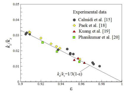
Figure 14 comparison between the prediction and the experimental data of the effective coefficient of through-hole foam aliminum(ke/ks=1/3(1-ε)),εis the porosity
5. Full analytical model for the heat transfer coefficient of close cell porous metal
Start with the Laplace’s equation that describe the temperature distribution inside/outside the hole, by solving the thermal field, we have got the effective heat transfer coefficient of the 2D periodic honeycomb and close cell foam aluminum which have randomly distributed ball-holes. Considering the effective heat transfer coefficient may change due to the change of the shape of the holes, we come up with the 3D particular solution that are modified by shape factor which is based on the spherical rate, thus we have got the full analytical model for the heat transfer coefficient of close cell porous metal as follows:
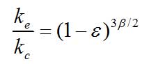
The 3D shape factors are shown as follows:
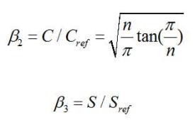
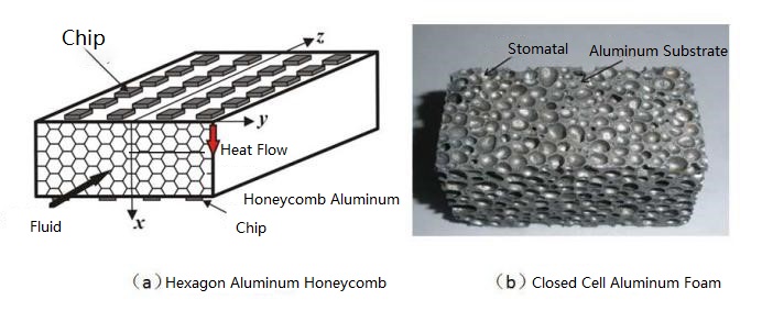
Figure 15 2D, 3D porous metal material
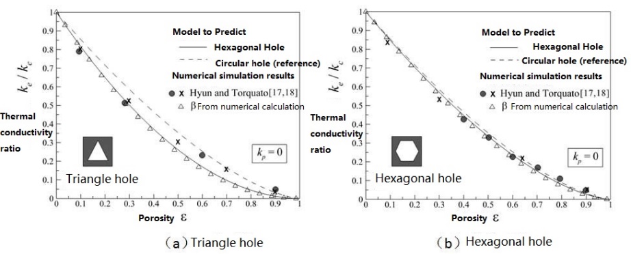
Figure 16 comparison between prediction and experiment on effective heat transfer coefficient of honeycomb aluminum with different hole shape
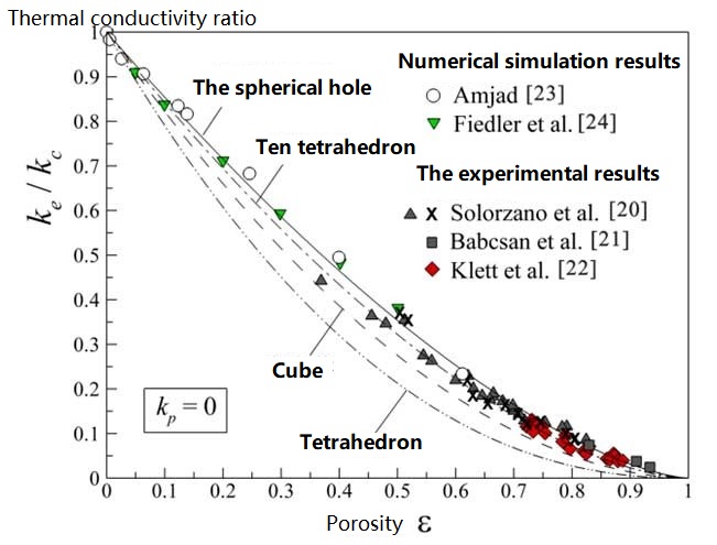
Figure 17 comparison between prediction and experiment on effective heat transfer coefficient of close cell foam aluminum with different hole shape
6. High temperature thermal protection properties of lightweight bearing/cooling multifunctional lattice metal sandwich structures
Lattice metal sandwich structures have both good load bearing ability and cooling ability, we can get good heat transfer properties if we choose the lattice metal as the deflector. We have developed a transient model for metal lattice structure under the impingement of hot gas (figure 19a), established the hot gas impinged jet and cooling testing platform (figure 19b). The experimental data can well coincide with the analytical prediction (figure 20), thus it has proved that the model is right.
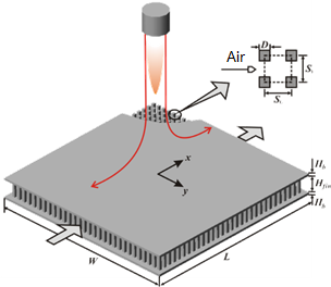
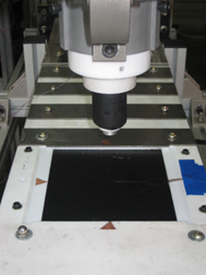
Figure 19 hot gas protection from lattice metal sandwich structure: theoretical model and testing platform
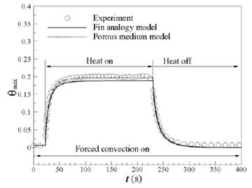
Figure 20 comparison between prediction and experiment for the thermal response curve of transient heat/cooling process
With the typical thermal loading of blast impulse, we give a prediction of the transient temperature distribution of metal lattice sandwich structure by a experiment modified model (figure 21). We have also give predictions regarding parameters of lattice core, radial heat transfer inside the panel, flow flux of the cooling fluid, meterial properties on the thermal protection. In the mean time, we have also analysed the heat transfer properties of lattice sandwich panel structure under the intermittent, periodic blast impinge, and got the periodic response regularity of temperature for the impulse panel (figure 22).
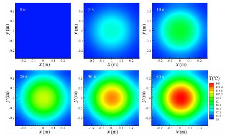
Figure 21 transient temperature distribution of lattice sandwich panel structures under the flame impact
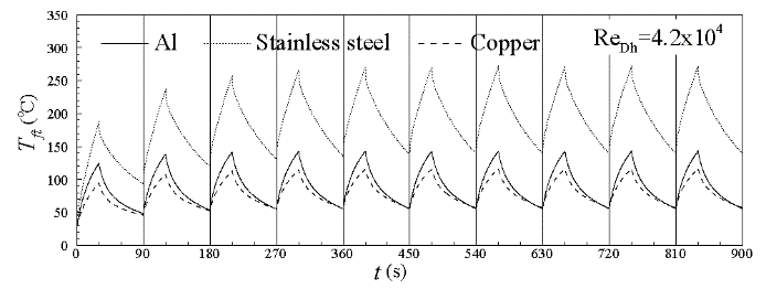
Figure 22 transient temperature response of the panel feature points under the periodic, intermittent flame impact
7. Heat transfer properties of through-hole metal foam under the impingement jet
With the electron device getting better and more integreted, some accompanying problems are increasing, which have lead to a need for compacted heat exchanger. Due to its ralatively larger area, 3D net-like structure and the irregular flow channel, the high porosity through-hole metal foam has a bright prosperous. Impingement jet has a better effect incooling and a more common appliance. Our job focus on the flow and heat transfer question problem of through-hole metal foam under the jet impingement.
1)flow visualization of metal foam under round jet
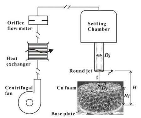
Figure 23 impingement jet testing facility

Figure 24 images of the flow field of free jet
Figure 23 has showed the impingement jet testing facility. Round jet will have different flow structures with s different Reynolds number. Figure 24 presents the images of the flow field of free jet of half-turbulant (Rej = 1,800)and tubulent(Rej = 7,500). There’s laminar flow inside the half-turbulant (a/Dj~12.0), only at the end of the laminar flow can we see the entrainment effect between the flow field and its surroundings. We cannot measure the length of potential core region. There’s no laminar in the turbulant and the potential core is distinctive(L/Dj=4.0).
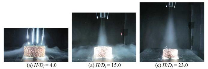
Figure 25 flow field of copper foam under the fully turbulant jet(Rej = 7,500)
Figure 25 shows that under the fully turbulant state, the increase of the impingement length is favorable for the permeation of jet fluid into the foam and may increase the heat transfer effect. But with the jet distance larger than some spacific distance, the cross sectional area is larger than the upper surface of the heat sink, which will cause the impingement jet unable to get into the inside of the foam and make the heat transfer property decrease when the distance reaches its peak.
2)flow and heat transfer properties of metal foam under the impingement of axial-flow fan
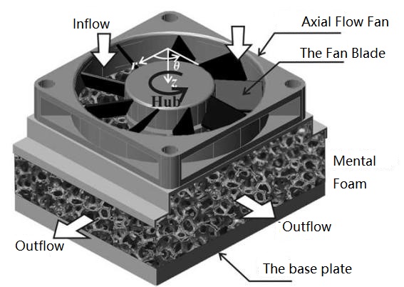
Figure 26 use metal foam as the extend surface for the cooling of electron device
Figure 26 shows the utilization of metal foam as the extend surface for the cooling of electron device.
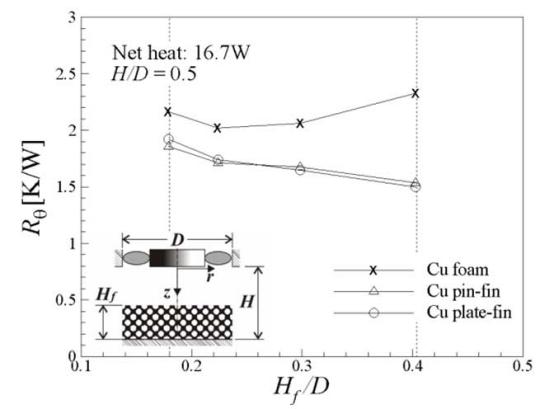
Figure 27 the heat resistance change of copper foam over the height of foam
Figure 27 shows that the through-hole copper foam with the optimized height has the lowest heat transfer resiatance. This is because that the foam has the biggest heat resistance when the height is large, this may prevent the cooling fluids from get inside the foam and thus the cooling fluid flux near the heat surface is decreased. The heat resistance of the typical fin heat sink and the fin-pillar heat sink will increase when the height decrease, which is different from the copper foam.

Figure 28 heat resistance of heat sink over impingement distance(H/Dj)
As shown in figure 28, in a given foam geight (Hf/Dj = 0.22), with a smaller impingement distance (H/Dj)the heat transfer property od copper foam can get increased. With the overall heat transfer performance remains, the weight of through-hole copper foam is 10% of copper fin heat sink or 30% of aluminum fin heat sink, while the volume is just a half of copper/aluminum heat sink.
8. Cooling on the trailing edge of a gas turbine
The efficiency of gas turbine will increase with a turbine inlet temperature(TIT) increasing, which will lead to a increase of temperature on the surface of the turbine blades. The TIT has increased from 1050K (1994) to 1750K (1994) according to the history of Rolls-Royce Trent. A more important way is to develop the cooling techniques for turbine blades cooling.
20% of the compressed air will be extracted to cool the blades, the cooling techniques can be devided into 2 catogories: 1. External cooling. Cool air will flow out of the small holes on the blade and form a qir film(as shown in figure 29a); 2. Internal cooling. Enforced flow inside the blade will take away the heat.(as shown in 29b);
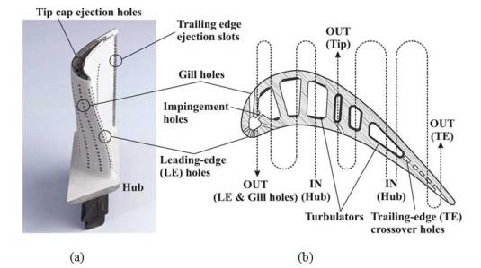
Figure 29 high pressure gas turbine blade;(a)blade with film cooling and thermal coating[2];(b)internal cooling system of the turbine blade, first-stage of E3,nasa

Figure 30 trailing edge cooling;(a)cooling structure with pin-fin;(b)simplified single pin-fin structure;(c)simplified infinite pillar
The velocity distribution and potential core can reflected the properties of flow field and have influence on the heat transfer abilities of impingement tube. Figure 31 includes the PIV image of flow field, velocity distribution in the different cross section area downstream and the velocity distribution in the axis. From the image, we can see that the length of the potential core is 4 times as large as the diameters of the impingement tube. After develops in the transition region, the flow will reach a fully development in which the axial speed is in reversely proportion with its distance from the outlet.
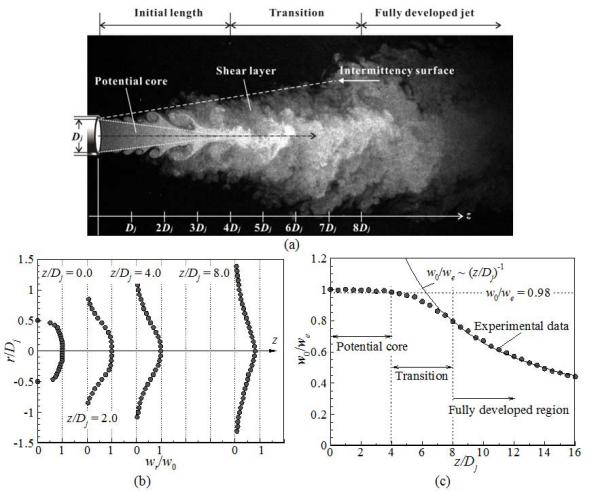
Figure 31 flow field of the impingement tube (Re=2000);(a)PIVexperiment;(b)velosity distribution in dofferent cross section downstream;(c)velosity distribution in the axis
Figure 32a shows the heat transfer distribution of the cylinder under the impingement jet and uniform flow, the regularity is different: with a boundary layer separation, the uniform flow will have a lowest point of heat transfer, while there will be a secondary peak in the potential core of the jet impingement. In conclusion, jet impingement is better for its less flow flux needed. In effect, with the same flow flux, the advantage may be more obvious.
Figure 32b analyses the influence of impingement tube skewing on the surface of the cylinder. With the offset, the stagnation point will move to the upstream of the geometric stagnation point, while the secondary peak in the uipstream may disappear. In the downstream region, the secondary peak will move in the downstream direction. All in all, increase for offset in the upstream region will impair the heat transfer ability, while increase for offset in the downstream region will enhance it.
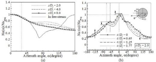
Figure 32 heat transfer temperature distribution on the cross section of the cylinder;(a)comparison of the two different cooling structures;(b)the influence of jet tube offset on the heat transfer property
Some research fruits achieved by our team will do good to engineering. In the meantime, there are still problems need to be solved.
Next page:Electromagnetic Properties